Changing the Color of Elements Based on Event Conditions
Scenario: You want to create an element that represents a room, an area, a device, and so on, that changes the color based on event conditions. In this example, the color of the area changes according to the value of an associated data point’s Event State.
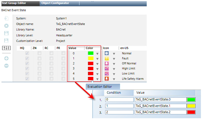
In this workflow, you must search the Text Group table for the property of the Life Safety data point; in this case, the point’s Event State property. In the table, each event state is associated with a value, and each value has an associated color. Taking this information you must create a Discrete evaluation for the Fill property.
Reference:
For background information, see Evaluation Expressions and Properties.
Workflow diagram:
Steps:
To configure an element that changes color based on event conditions, you must search the Text Group table for the property of the associated data point.
For example, the color of the area changes according to the value of an associated data point’s property; in this case, the Event_State of a Life Safety data point. In the Text Group table, each event state is associated with a value, and each value has an associated color related to a condition. Noting this information, you must create a Discrete evaluation for the Fill property.
- For easier viewing and navigation, launch a second System Manager pane. Navigate to the Desigo CC system Menu in the upper-right corner of the pane, and then select Applications > Start New System Manager Browser.
- A second instance of System Browser, labeled System Manager (2) is created. You can now switch between the new instance and any other window from the Windows taskbar or from the system Menu > Active tasks.
- Click Operating to switch to Engineering mode.
- In System Browser, select Management View.
- Navigate to the data point you want to command or monitor. In this example, a Life Safety data point.
- In the Object Configurator tab, in the Main section, double-click the Object model text.
- Click the Models and Functions tab, and in the Properties section, click the property you will use to monitor on your graphic, and in the evaluation. In this example, click Event_State.
- In the Details section, double-click the Text group text.
- In the Text Group Editor tab, the associated text group displays.
- Note down the following information:
- Object name for future reference. This is the text group name you will refer to in your evaluation in the Graphics Editor. In this example:
TxG_BACnetEventState.
- The Value column represents the integer values that are associated with the colors, and assigned to the Event_State property of the Life Safety data point.
- Exit out of Text Group Editor and the Models and Functions tab.
You have an element on your graphic; it can be a part of a floor plan or represent an area or a device. You want to configure an element’s color property (Fill, Stroke, or Background) to change based on event conditions.
In this procedure, the Event_State of a Life Safety data point is used to apply the Fill color to the element on the graphic.
- System Manager is in Engineering mode.
- You have the name of the Text group table that represents the various states of the data point property you are monitoring.
- Click a drawing element and then draw a desired shape for the element. If you already have an element on the canvas that represents the area or device you want to monitor, proceed to Step 2.
- Select the element on the canvas, and from the Property View, expand the property whose condition you want to monitor. In this example, expand the Colors section and select Fill.
- In the View tab, place a check mark next to the Evaluation Editor.
- The Evaluation Editor view displays.
- From the Property drop-down menu, select Fill, and then from the Type drop-down menu, select Discrete.
- In System Browser, select the designated data point that you want to monitor, and then do one of the following:
- Drag the data point to the Evaluation Editor’s Expression field and at the end of the expression type a period “.”, followed by the property name. In this example:
.Event_State.
- From the Extended Operations tab, navigate to the data point’s property that is receiving the evaluation, and then drag the property into the Expression field. The data point with the appended property name display in the field. In this example, navigate to the Event State property.
- In the Condition field, use the integers from the Text Group table associated with the property of the data point you are monitoring. For each condition, do the following:
- In the Condition field, enter the integer from the Text Group table. For example:
0.
- In the Value field, type the Text Group table name and then [.] and the corresponding integer value. For example:
TxG_BACnetEventState.0.
- To add a new Condition row, click Insert New Condition.

- Click Save.
