Modbus Workspace
The Modbus Workspace provides information on the UI components for creating drivers, networks, importing devices, and so on.
A Modbus driver is needed to connect modbus devices with the management platform. The management platform starts with no Modbus driver defined. In the Engineering mode, you must add it as needed, from the Object Configurator tab under Management System > Server > Main Server > Drivers, when you select Management View in System Browser.

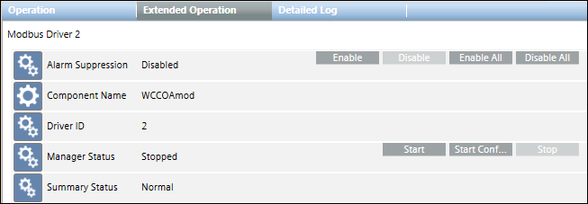
From the System Browser tree, when you select the Modbus Driver node (in Engineering/Operating mode), the Operation/Extended Operation tabs display the Start and Stop commands that you can use to start and stop the driver. The Stop command is only enabled when the driver is running; it is disabled if the driver is not running or an operation is in progress.
For the main server, the default project provides a Drivers folder. However, if the management platform you configure includes FEPs, you must configure FEP to add a FEP station. Under the FEP station, you must then add a Drivers folder for adding a driver. You can only add a driver in Engineering mode.
After creating the Modbus driver, you must start it and link it to a Modbus network.
To delete the Modbus driver, you must first delete all the Modbus networks attached to the driver. Once you delete the respective networks, you can delete the driver by selecting the Object Configurator tab and clicking Delete .
.
You can have 10 drivers running simultaneously per server. A maximum of 35000 points can be associated with each driver.
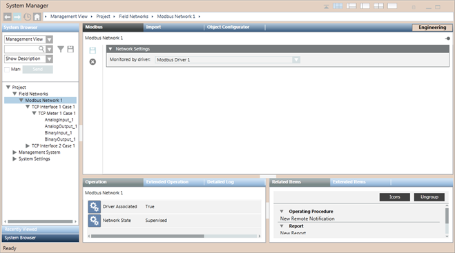
In Engineering mode, after selecting a Modbus network in System Browser, you can configure its network settings using the Network Settings expander of the Modbus tab. You can only delete the Modbus network. The properties associated with the selected network display in the Operation/Extended Operation tabs.
You can set the Poll interval. The default value is 0 ms.

Modbus Toolbar | ||
Icon | Name | Description |
| Save data | Saves any changes. |
| Delete object | Deletes the current object. |
Network Settings Expander
The Network Settings expander allows you to define the Modbus driver monitoring a Modbus network.
Network Setting Expander Fields | |
| Description |
Monitored by driver | Select a Modbus driver. Once you associate a driver to a network, you cannot delete that driver. |
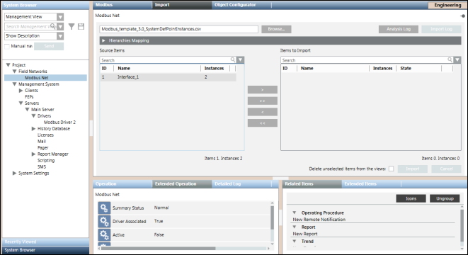
The Import tab allows you to manage the import of field data (engineering objects) described in Modbus configuration files (CSV file).

NOTE:
Power Devices must be integrated in Desigo CC only by the Powermanager extension.

Import Fields | |
| Description |
Browse | Displays the Open dialog box where you can select a file to import. |
Source Items | Displays all the objects available for a selected file, identified by the following:
|
Items to Import | Displays all the objects selected for the import, identified by the following:
By default, this section is empty. Move the items from Source Items to Items to Import or vice versa by double-clicking the single item, or using the buttons that provide tooltips suggesting the action to take. |
Search | Apply a filter to the content of the corresponding list (Source Items or Items to Import). Delete the text in this field to remove the filter. |
Analysis Log | Opens a log displaying the file reading and pre-process operations. This log also contains the time for the operations, the name of the processed files, and warnings/errors (if any). |
Delete unselected items from views | Specify whether or not, during the import, all the items available in the Views but not mentioned under the Modbus interfaces present in the file to import must be deleted. |
Import | Start the import. |
Import Log | Opens a log of the import operation. This button is only available when the import is successfully completed. |
Cancel | Abort the import. This button is available only during the import. |
Hierarchies Mapping Expander
Once you have extracted a CSV file to import, the Hierarchies Mapping expander allows you to define the root node for each hierarchy and for each System Browser view.
The Hierarchies Mapping expander allows you to configure the destination in the system views of the data structures (hierarchies) imported according to the import rules.

Hierarchies Mapping Expander Fields | |
Field | Description |
Hierarchy Name | Displays the hierarchy name. |
Import this hierarchy under this node | Displays the hierarchy import rule (for example, the Hardware hierarchy was assigned to the Management View). |
Re-Import the Modbus Objects
When re-importing Modbus data using a CSV file, the re-import applies to the Modbus interfaces, devices and their field points referred to in the CSV file.
The re-import operation is done in a similar way as the import, except that the pre-existing Modbus objects are updated as follows:
- Creating new data points.
- Updating existing data points.
- Deletion existing data points (only if the Delete unselected items from the views check box is selected).

NOTE:
Deleting the Modbus points results in deleting them from all the hierarchies in other views.
This operation also causes the Management View hierarchy to add objects and internal nodes (points), and delete internal objects. The import process deletes any Modbus devices that are no longer present in the CSV file (only if the Delete unselected items from the views check box is selected).
Dropping of Workstation Alarms during Re-import
Workstation alarms can be dropped or removed from any existing Modbus point by re-importing the same point using a CSV file that does not contain the alarm entry for the corresponding point.
A workstation alarm entry is defined by the AlarmClass, AlarmType, AlarmValue, EventText and NormalText fields. You must manually delete these fields that correspond to the point for which you want to drop the workstation alarms.
Modbus interfaces are imported under the following path: Field Networks > Modbus Network in Management View of System Browser.
Before importing Modbus interfaces, the Modbus network must be available.
In System Browser, each Modbus network contains a set of Modbus interfaces and each of them contains the devices and points attached to that interface.
Communication Interface Expander
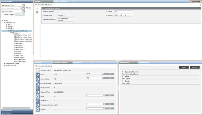
In Engineering mode, when you select a Modbus interface in System Browser its settings display in the Communication Interface expander in the Modbus tab. You can save the data or delete the Modbus interface.
Modbus Toolbar | ||
Icon | Name | Description |
| Save data | Saves any changes. |
| Delete | Deletes the current object. |

Communication Interface Expander Fields | |
Name | Description |
Interface ID | Displays the interface instance number (read only). |
Interface name | Name of the interface. (read only). |
TCP port | Displays the TCP port number assigned to the device in the network. You can modify this field. |
IP address | Displays the hardware address of a device connected to a network that uses Internet Protocol (IP) for communication. You can modify this field. |
Communication Interface Properties | |
Property Name | Description |
Summary Status | Displays the summary status |
Active | Displays the connection status of the device. It can have two values: |
Frame Coding | Type of FrameCoding supported by the device. It can have either of the following values: Default value is TCP, however, you can set a different value as per the device specification. |
Connection State | Connection state of the device. |
Driver Number | Driver ID to which the connection object is linked. |
Hosts and Ports | Host ID and port number of the device. |
Offset | This data point element allows for defining the offset. Default value is 0 but you can set a different value. |
Interface ID | Displays the interface ID |
Transaction Timeout | The timeout period between a request and response. This period is specified in milliseconds (100-100000). In the event of a timeout, the request is lost and the connection is closed. The connection can only be re-established at the next request. |
Slave ID | Slave ID of the communication interface. |

