CSV File for Modbus Device Import
To create instances of the Modbus devices and data points, you must create the engineering data in the form of a comma-separated value (CSV) file.
A CSV file template example named Modbus_template_4.0_SystemDefPointInstances is provided under the following folder GmsMainProject\profiles\ModbusDataTemplate. This CSV file can be used to start your data input.
A CSV file contains data in which values are represented as text and separated using a separator such as comma (,).The file in the CSV format can be edited in simple text editors. The importer can parse CSV files. You can add comments to the CSV file, such as an explanation about the engineering data.
The content of the engineering data is partly dependent upon the workflow chosen. When creating object instances using standard Modbus object models, the engineering data is structured as follows.
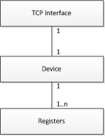
The above relationship can be described as a device that contains a number of data points and uses a unique TCP interface. The relationship between the communication interface and the device is one-to-one which means that each device has its own TCP interface. However, when a number of Modbus RTU devices are integrated using a TCP gateway, there is only one physical communication interface, which is used by more than one device. In this case, the engineering data still contains a unique interface declaration for each device. A communication interface is a unique combination of an IP address and a slave address. The following example illustrates how a single device and its required registers are assigned in the engineering data.
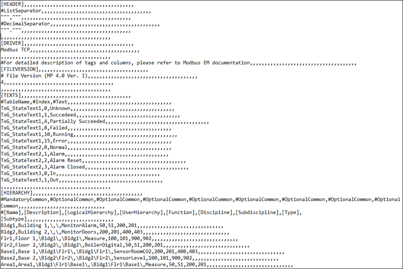
At this point, the interface, device and data points are interlinked using the same attribute.
Points to remember while editing a CSV file in Microsoft Excel
- If you use a semicolon as a column separator in the CSV file, then the decimal separator must be a period. Otherwise, the data is saved in the wrong format (for example, 1.1 becomes 01.Jan; 2.6 becomes 02.Jun).
- The decimal separator is available only in advanced options of Microsoft Excel.
- When using negative values in Microsoft Excel cells, you must use the character ’ .
- For the Resolution value, decimal numbers must be applied in the format xx.xxx; otherwise, the wrong value is interpreted by the Importer.
- The elements of the CSV file must be added in the CSV in the following order: interface, device and point. Changing the order may cause the Importer to reject the entry. The Importer interprets fields based on their order and not according to the column headers, for example, [InterfaceName], given in the CSV file. Column headers are provided only for informative purposes but do not have any significance for the importing process.
- A comment line is marked with the character #. # marks the starting of a row with headers. # denotes comments, meaning that the Importer ignores the row.
- The elements in the CSV file cannot include spaces, or a semicolon: (;).
The following special characters will be replaced with an underscore (_):
- @, - $ , - * , - - , - : , - ?, , -
You can convert an older version of the CSV file to a newer version using the ModbusCSVConverter utility. This conversion is required when you must upload the data from an older version of the CSV file to the management station. Instead of copying the data from the older version of the CSV file and manually pasting it to the new format, you can use the ModbusCSVConverter.
This utility is available in the bin folder of the GMSMainProject folder of your machine. You can execute this utility by performing the following step:
- From the Windows Explorer, double-click the Siemens.Gms.Modbus.ModbusCsvConverter.exe file. In the command prompt that displays, drag the CSV file to be converted. This file is converted to the new format and the converted file is placed at the same location of the source CSV file with the text _converted appended to its name. If the destination file already exists, then the new CSV file will have a number appended to it. For example, [Name of the CSV file]_converted_1. This number will increase by 1 each time the converter finds an existing file with the same name.
Updates Performed to the Existing Data During Conversion
- If the old format of the CSV file contains a value in the Function column, which is also known as Function Key, then this value is not transferred to the new version of the CSV file during conversion, as the new format does not support the Function Key anymore. However, this results in a loss of data, although you might not notice this automatic omission. To resolve this issue, the converter automatically adds the following content in the Function column of the converted CSV file. Thereafter, you must refer to the Function Key from the older Import Rules and copy the corresponding values of Function, Discipline, Subdiscipline, Type, and Subtype.
- Converting Text Group Strings – The converter will convert the text group string present in the StateText column by performing the following steps:
- Convert the text group string from the StateText column into its individual indices and statetexts (using the Min value as the starting index). For example, if you have State1$State2$State3 with the Min value as 0, the converter will break this string into the following three statetexts: State1, State2, and State3 and assumes the index of the first entry is 0.
- Using the text group name starting with "TxG_Project_Modbus_", the converter will create entries into the Text section. Using the preceding example, the text group name will be “TxG_Project_Modbus_State1_State2_State3” and the entries will be as follows:
TxG_Project_Modbus_State1_State2_State3,0,State1, TxG_Project_Modbus_State1_State2_State3,1,State2, TxG_Project_Modbus_State1_State2_State3,2,State3 - Replace the value under StateText column with the text group name, that is TxG_Project_Modbus_State1_State2_State3.
- The converter adds the delimiter '\' at the beginning of the existing logical and user hierarchy strings. For example, the string "Building1\Floor1\" will be changed to "\Building1\Floor1\".
If the ObjectModel field is specified for a device or data point, the Importer will create a data point based on the specified object model and will configure the addresses according to the custom Import Rules definition. A CSV file can have definitions of both devices and data points referring to a custom object model, as well as devices and data points without any object model specified (which results in instances of the standard object model).
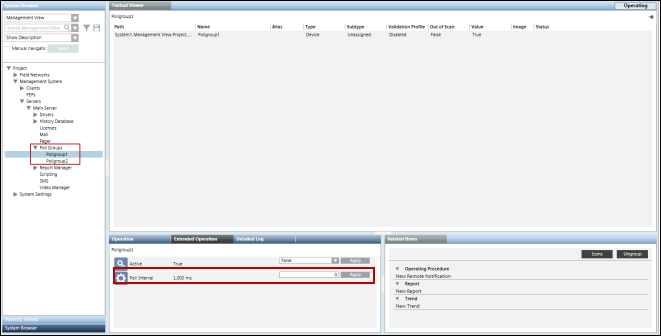
When importing the CSV file that has an object model specified in the ObjectModel field, then the pollgroups assigned to the object model properties in the custom import rules will be imported at the following location, Project > Management System > Servers > Main Server > Poll Groups.
If you need to modify the poll group intervals at any time, you can do so from the Extended Operation tab by specifying the new interval and clicking Apply.
If a data point with input direction does not have a pollgroup assigned or the assigned pollgroup is not present in the custom import rules, then the pollgroup specification is taken from the network node during import of the CSV file.
If the name of the address profile is specified for a particular object model in the CSV file, the address configuration associated with the specified address profile in the Objects and Properties expander will be considered during import.
However, if no name of an address file has been specified, the address profile set as default for the object model in the Objects and Properties expander will be considered during import.
In case of custom points, the value for Low Level Comparison will always be taken from the Custom Import Rules irrespective of whether or not this value is specified in the CSV file.
The following example shows a CSV file which has a combination of such definitions.
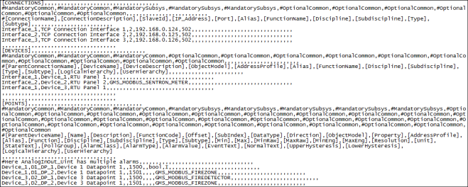
In the above example, the Importer will create the following instances:
D1_DP_1 results in an instance of GMS_MODBUS_BINARY_INPUT (an object model in the HQ standard library)
D1_DP_2 results in an instance of GMS_MODBUS_FIREZONE and the property addresses is constructed according to the custom Import Rules (taking 1501 as base address).
Note that Device_1 can contain data points based on a mix of standard and custom object models.
D2_DP_1 results in an instance of GMS_MODBUS_FIREDETECTOR and the property addresses is constructed according to the custom Import Rules (taking 1500 as base address).
D2_DP_2 results in an instance of GMS_MODBUS_FIREZONE and the property addresses is constructed according to the custom Import Rules (taking 1501 as base address).
To illustrate the above approach, the following two CSV files are included. These files are to be found under GmsMainProject\profiles\ModbusDataTemplate.
- Modbus_template_4.0_CustomObjectModel.csv - This file contains a sample custom object model. Each property of this object model has a corresponding output property to support the InOut properties feature.
- Modbus_template_4.0_InOutAndCustomPointInstances.csv - This file contains instances (or points) of the custom object model defined in the above CSV file. It also contains instances of the InOut object models.
Offset Field for Custom Object Models
If a data point in the CSV is specified with a custom object model, then the value in the Offset field is added to the Offset specified for the property in the Import Rules. The following example illustrates this concept. Assume there are two data point declarations in the CSV:
Device_2,DP1,Dp1 of Device_2,,1502,0,,,MyDevice,,,,,,,,,,,,,,,,,,,,,,,,,
Device_2,DP2,Dp2 of Device_2,,1506,0,,,MyDevice,,,,,,,,,,,,,,,,,,,,,,,,,
Suppose the custom Import Rules specify the following for the properties of Object Model GMS_MODBUS_FIREZONE.

In this case, the Importer will address the data point properties as:
DP1.Alarm will be addressed to use register type 01 and offset 1502
DP1.Status will be addressed to use register type 01 and offset 1503
DP2.Alarm will be addressed to use register type 01 and offset 1506
DP2.Status will be addressed to use register type 01 and offset 1507
In case of Blob data type, the syntax of the Offset will be <OffsetValue>:<Size>.
For example, if your blob property has an offset value of 64 and size of 16 bytes then in the Offset field, specify the value as 64:16.
N to 1 Mapping
The concept of N to 1 mapping is used in situations in which you want to assign the address to specific properties of a custom defined object. The properties to which the address is to be assigned are specified in the [Property] field next to the [Object Model] in the [POINTS] section of the CSV.

In this example, we will assign address to Property 1, Property 2, Property 3, and Property 4 of the GMS_LIFT custom object model.
In case of N to 1 mapping, the Transformation Type of the device properties are set as per the value of the datatype provided in the CSV file.
This section includes important points to consider before importing the CSV file.
Multiple Modbus Interfaces Under Same Gateway
- In a Modbus network, every device must have a Slave Id under a given IP address. The Slave Id must be unique.
- If two or more Modbus interfaces have the same IP address, this means they are connected to the same gateway. In this case, the Slave Ids must be unique. However, the same Slave Id can be repeated for interfaces that have different IP addresses.
- If two or more Modbus interfaces have the same IP address, as well as the same Slave Id, then the Modbus Importer will issue an error during the import and skip importing the affected device and its points.
- There is no representation of the gateway object in the System Browser tree. Therefore, there is no such gateway object in the hierarchy above the Modbus TCP interface if they belong to the same gateway.


Effect of Duplicate Slave ID During an Import
Assume that you have imported the following CSV file. This file contains two interfaces with the same IP address, but different Slave Ids. The protocol interprets these to be devices under the same gateway.
This CSV file will be imported without errors, creating the corresponding instances in the system.

Assume the import was successful, and you try to import a CSV file with the same IP address and Slave Ids, but different Interface and Device names (highlighted below). The importer allows you to import this CSV as well.

Interface_1 from the previous CSV and Interface_11 from the following CSV now have the same IP address and Slave Id. Since they have the same IP address, it indicates they are under the same gateway; therefore, they cannot have a duplicate Slave Id. However, they have the same Slave Id of 1. As a result, during runtime, only one of these interfaces can connect to the driver, while the other remains disconnected.
Therefore, when importing new instances in the system, the same Slave Id must not be duplicated under the same gateway.
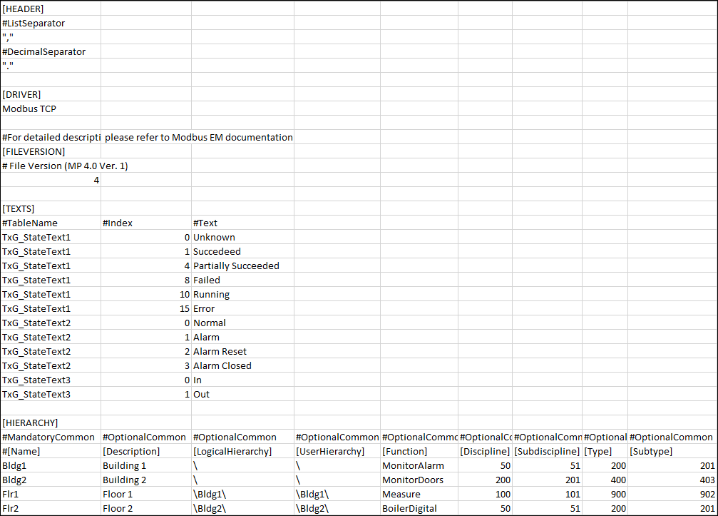
The CSV file comprises of the following sections:
[HEADER]
Contains two separators, a List Separator and a Decimal Separator. Both these separators are placed in the same sequence on two subsequent lines. These separators are placed inside quotes for easy identification.
The List Separator is used as a delimiter for parsing of row data in the CSV file.
The Decimal Separator is used for parsing of fields having values as floating point numbers. These fields include the following, Min, Max, Scaling Factor (MinRaw, MaxRaw, MinEng, MaxEng), and Alarms.
[DRIVER]
Specifies the name of the subsystem (For example, Modbus TCP) to which the CSV file is associated with.
[FILEVERSION]
Displays the current version of the CSV file.
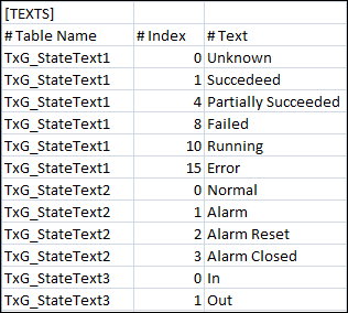
[TEXTS]
Allows you to add a new text group to the system.
| Description |
Table Name | Name of the text group. |
Index | An integer value representing the different states of the text group. |
Text | Text associated with each integer value of the text group. |
[HIERARCHY]
Allows you to specify the classification attributes (Discipline, Subdiscipline, Type, Subtype, and Function) to the aggregator nodes in the Logical and User hierarchy levels. The classification attributes are associated with the respective aggregator nodes in the Logical and User hierarchy levels on importing the CSV file.

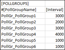
[POLLGROUPS]
Allows you to import poll groups to the system.
Item | Description |
Poll Group Name | Name of the poll group to be imported in the system. The name of the poll group must begin with the following mandatory prefix: PollGr_. The poll group is not created in the system if the prefix is missing. |
Interval | Time interval for the poll group. |
Important Points to consider for Poll Group Import
- Poll groups are applicable only to the points where the Direction field is set to Input.
- If the [POLLGROUPS] section is available in the CSV file but there are no poll groups assigned to the points, all poll groups listed in the [POLLGROUPS] section will be imported into the system. After import, they will be added to the following location, Project > Management System > Servers > Main Server > Poll Groups.
- If the poll groups assigned to the points are listed in the [POLLGROUPS] section, the poll groups will be added to Project > Management System > Servers > Main Server > Poll Groups and assigned to the respective points after the import of the CSV file.
- A poll group listed in Project > Management System > Servers > Main Server > Poll Groups, but not listed in the [POLLGROUPS] section in the CSV file is associated with a point in the CSV file, then the poll group is assigned to the point after import. If the poll group is neither available in the Poll Groups folder nor listed in the [POLLGROUPS] section, an error message will be issued on parsing the CSV file.
- If a data point with input direction does not have a poll group assigned or the assigned poll group is not available in the CSV file or in the Project > Management System > Servers > Main Server > Poll Groups node, the poll group specification is taken from the network node during the import of the CSV file.
- If an existing poll group that is not listed in the [POLLGROUPS] section, but is present in Project > Management System > Servers > Main Server > Poll Groups, is associated with a point in the CSV file, then the poll group will be is assigned to the point in the system after import.
[LIBRARY]
Multiple standard Modbus libraries can exist in the system. You can use these libraries to define standard Modbus points in your network. You can import Modbus points according to the object models defined in the library.
The Modbus library tag refers to a standard Modbus library. This tag is mandatory; however, you can ignore it if the CSV file contains the points for custom object models only. In order to find the name of the Modbus library, see Verifying the Modbus Library.
The Modbus library is defined using the following field.
Modbus Library Data | |
| Description |
LibraryName | Name of the Modbus library. |
[CONNECTIONS]
The connection is defined using the following fields (strictly in this order).
Modbus Connection Data | |
| Description |
ConnectionName1) | Name of the Modbus connection instance. |
ConnectionDescription1) | Description of the Modbus connection instance. The same description will be set for all the available languages of the project. |
SlaveID1) | Unique number given to the connection, if it is connected to the gateway using the same IP address and port. This field must be numeric and greater than 0. |
IP_Address1) | IP address of the connection connected to a network. This field should be in the format xxx.xxx.xxx.xxx, where x is numeric. Valid values are 0 through 255. After the import, you can change this field from the Modbus interface workspace. |
Port1) | TCP port number to be assigned to the connection. Valid values are 0 through 65535. |
LittleEndian | Specify the Endianity of the Modbus device. |
Active | Specify if a connection with the device is to be established. It can have either of the following two values: False: No connection with the device will be established. Default value is True |
Offset | This data point element allows to define the offset. Default value is 0 |
FrameCoding | Specify the type of frame coding supported by the device. In general the following types of frame coding is supported, ASCII, RTU, TCP. The exact value supported by the device is available in the device manual. The default value is TCP. |
Alias | Alias assigned to the connection. |
FunctionName | Name of the function to which the connection is associated with. |
DisciplineID | Discipline to be associated with the connection. |
SubdisciplineID | Subdiscipline to be associated with the connection. |
TypeID | Type to be associated with the connection. |
SubtypeID | Subtype to be associated with the connection. |
1) | Indicates Mandatory Field |
[DEVICES]
The device is defined using the following fields (strictly in this order).
Modbus Device Data | |
| Description |
ParentConnectionName1) | Name of the connection to which the device is connected. It must be the same as the ConnectionName of the where this device should be connected. |
DeviceName1) | Name of the Modbus device instance. The naming rules are similar to those for InterfaceName, that is, no spaces or special characters. |
DeviceDescription1) | Description of the Modbus device instance as it will appear in System Browser (Management View). |
ObjectModel | Object Model of the device if it is a custom device. |
AddressProfile | AddressProfile associated with the object model. |
Alias | Alias assigned to the Modbus device. |
FunctionName | Name of the function to which the device is associated with. |
DisciplineID | Discipline to which the device is associated. |
SubdisciplineID | Subdiscipline to which the device is associated. |
TypeID | Type of the Modbus device. |
SubtypeID | Subtype of the Modbus device. |
LogicalHierarchy | Logical Hierarchy of the device in the logical view. The logical hierarchy path in the CSV file must start and end with a backslash (\). |
UserHierarchy | User hierarchy of the device in the user-defined view. The user hierarchy path in the CSV file must start and end with a backslash (\). |
1) | Indicates Mandatory Field |
[POINTS]
The data point (register) is defined using the following fields (strictly in this order).
Modbus Point Data | |
| Description |
ParentConnectionName1) | Name of the Modbus connection instance. |
ParentDeviceName1) | Name of the device to which this point is connected. It must match the DeviceName of the device to which this point will be connected. |
PointName1) | Name of the Modbus point. The naming rules are similar to that of InterfaceName; there must be no spaces or special characters. |
PointDescription1) | Description of the Modbus point instance as it will appear in System Browser in Management View. |
FunctionCode1) | Modbus function code for accessing Modbus data points. It should be numeric and must be from the set of FunctionCodes mentioned in the Import Rules. It is mandatory for system-defined points, but optional for custom points. |
Offset1) | Offset number defines the address of point in the set of data points. For example, the offset 0 indicates address 1. The Offset must contain numbers greater than or equal to 0. For example, if your blob property has an offset value of 64 and size of 16 bytes then in the Offset field, specify the value as 64:16. |
SubIndex1) | Subindex value specifies the starting bit from which to read or access a part of the retrieved data point value. Composed of byte streams, the Modbus data is an array of untyped values. Subindex value defines the position within that array. Using Subindex and its transformation type, the Modbus data point calculates the number of bytes to be taken from that position. |
DataType1) | Transformation type. Data format required by the Modbus device. |
Direction1) | This defines the address/response mode used for accessing the value on the Modbus server: |
LowLevelComparison | Low Level Comparison is applicable for only those properties with Direction as Input. The default value of this field is False. If set to True, the driver sends the data only in case of changes. |
ObjectModel | Object model of the point if this is a custom point. |
Property | Name of the object model property. |
AddressProfile | Address profile associated with the object model. |
Alias | Alias to be assigned to the Modbus data point. |
FunctionName | User-defined function. |
DisciplineID | Discipline to which the Modbus data point should be associated with. |
SubdisciplineID | Subdiscipline to which the Modbus data point should be associated with. |
TypeID | Type of Modbus data point. |
SubtypeID | Subtype of the Modbus data point. |
Min | Minimum value set for a field point. The syntax depends on the mentioned data type. If it not present, then it is taken from the object model. |
Max | Maximum value set for the field point. The syntax depends on the mentioned data type. If it is not present, then it is taken from the object model. |
MinRaw | Lower end of the raw value scale. |
MaxRaw | Upper end of the raw value scale. |
MinEng | Lower end of your engineering value scale. |
MaxEng | Upper end of your engineering value scale. |
Resolution | The number of digits that display after the decimal point (resolution value). |
Unit | Selection list for a unit from the selected text group. (For example, %, min, °C, and so on). If it is blank, then no unit is set for this point. |
StateText | Name of the text group. This text group could be either from the list of text groups defined in the Texts section or from the text groups present in the system. This field applies only for BOOL and ENUM data types. |
PollGroup | Name of the poll group to be associated with the point. |
AlarmClass | Generic Alarm class. |
AlarmType | Workstation Alarm Type |
AlarmValue | Defines the value for which an alarm is reported. The range is indicated by the $ character. For example, if the Alarm Value is 40$50, it means that alarm values are between 40 and 50. |
EventText | Alarm text for incoming event. For multiple alarms, multiple event texts can be defined. |
NormalText | Alarm text for outgoing event. For multiple alarms, multiple normal texts can be defined. |
UpperHysteresis | Defines the upper range for the alarm value; beyond which alarms will be generated. For example, if the alarm set for the value is greater than 50 and the UpperHysteresis is set to 2, then the alarm is only generated when the alarm value reaches 52. |
LowerHysteresis | Defines the lower range for the alarm value below which alarms will be generated. This value is always specified as a negative. For example, if the alarm set for the value is less than 50 and the LowerHysterisis is set to -2, then the alarm is only generated when the alarm value falls to less than 48. |
NoAlarmOn | Defines whether or not an alarm is triggered whenever the connection to the device is lost. This field can have either of the following values: |
Logical Hierarchy | Logical Hierarchy of the data point in the logical view. The logical hierarchy path in the CSV file must start and end with a backslash (\). |
User Hierarchy | User hierarchy of the data point in the user-defined view. The user hierarchy path in the CSV file must start and end with a backslash (\). |
1) | Indicates Mandatory Field |

NOTE 1:
If any of the alarm fields contains an error, the point is imported, but no alarm is configured.
NOTE 2:
If multiple alarm configurations are listed in one field, the delimiter is $.
NOTE 3:
The following data point fields are ignored from the CSV file if the object model is present or it is not empty because the Importer interprets this point as an instance of a custom object model and expects that all these settings are already configured in the object model.
- Function Code
- DataType
- Direction
