In the System Browser, select the ESPA Paging System driverand click the Driver Editor tab.
(Optional) In the Driver Settings expander, modify the description.
In the Configuration Properties expander, proceed as follows.
In the Device Request Timeout field, enter 10000 (value inmilliseconds).
In the the Check Status Rate field, enter 30000 (value inmilliseconds).
In the Notification Integration expander, proceed as follows.
Set the Batch Size fieldvalue as 50 (default is 100). Batch size specifies the size in which the request is processed by the driver. The batch size displays the number of devices to which Notification interacts in one instant. For example, if there are 100 devices on which a message has to be displayed and a batch size of 10 is entered, Notification will send the message to batches of 10 devices each.
Enter a value into the Expected delivery time field (default is 10 seconds). NOTE:Notification does not guarantee the message delivery will be completed within the time entered in the ExpecteddeliveryTime field. This value is solely used to compute delivery statistics indicating whether message delivery to the ESPA Paging System server was on-time or late.
On-Time or Late displays are based on the time it takes for Notification to deliver the message to the ESPA 4.4.4 server and not the time taken to deliver the message to the actual recipient.
Click Save.
The parameters are configured for the ESPA Paging System driver.
Click New object and select New ESPA Paging System Field Network.
The Create New Object dialog box displays with the Child type field pre-set to ESPA Paging System Field Network.
Enter a name and description.
Click OK.
The ESPA Paging System field network node displays in the field network hierarchy and is selected by default.
The ESPA Paging System driver is automatically associated to the field network. In the Network Editor tab, under the Network Settings expander, you can see that the values are preselected, and the driver is already assigned.
Enter the COM port address of the device in the Serial Port Number field. You should enter a valid COM port address string of the device.
From the Device Mode drop-down list, select Operational so that the driverprocesses the messaging command and the device configuration change command, and performs status checks for the device. You can also select the following: - Disabled: In this mode, the driver does not process the messaging command, or the device configuration change command, and can perform status checks for the device. The device remains in a disconnected state. - Administrative: In this mode, the driver processes the device configuration change command and performs status checks for the device. The device will be in a Disconnected/Connected state based on the connection state.
Enter the ID assigned to the device in the Device Id field.
Select the Baud Rate the device is using serially from the drop-down list.
Select the Parity, the device is using from the drop-down list.
Select the number of Stop Bits, the device serial protocol is using from the drop-down list.
Select the number of Data Bits, the device is using to communicate serially. NOTE: The value range is 5 to 8 bits.
Enter the number of attempts, a message should be sent by the ESPA managed device to the corresponding recipients in the No. of Transmissions field.
Enter the default value of the number of transmissions of the ESPA managed device in the Default No. of Transmissions field.
Select the default values of call types for the ESPA managed device from the Default Call Type field. The details of each call type are mentioned below: 1 - Reset (cancel) call 2 - Speech call 3 - Standard call
Enter the default value of priority for the ESPA managed device in the Default Priority field.
Map the message priority with the ESPA 4.4.4 priority values in the ESPA 4.4.4 Priority Values field. NOTE: For every message priority select ESPA 4.4.4 priority values. For example, a notification priority High can be associated with ESPA 4.4.4 priority value Alarm (Emergency).
Contains the default value of beep coding records for the ESPA managed device in the Default Beep Coding field.
Maps the message type with the beep coding values from the Beep Coding Values field. NOTE: For example, a message type of Life Safety Alert can be associated with Beep coding value 5.
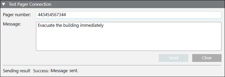
In the Test Pager Connection expander, you can send a test text message.
Enter the pager number and message in their respective fields.
Click Send to send the test message.
The sending result displays in the expander after the message is sent.
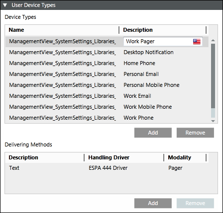
The user device type is automatically configured. In the Recipient Editor tab, under the User Device Types expander, you can see that the ESPA 444 Driver is set as the handling driver and modality is set as Pager.
Once the incident is initiated, the recipient user in the message template receives pager message with the content as described in the corresponding message template. The initiate incident is performed using Command and Reaction.
 and select New ESPA Paging System Driver.
  .
. and select New ESPA Paging System Field Network.
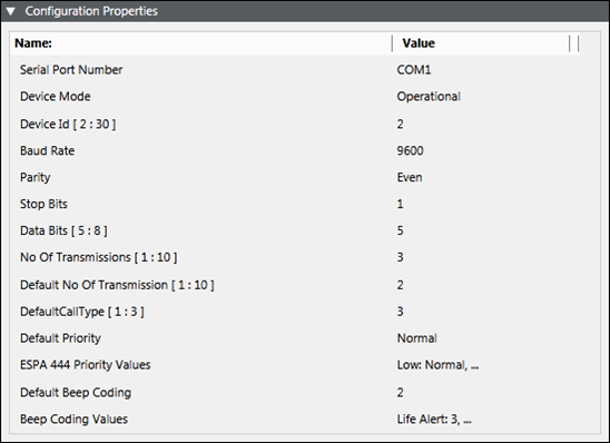
 .
.